上QQ阅读APP看书,第一时间看更新
1.7 F28335的引脚与封装图
F28335芯片有3种封装:一种是176引脚PGA(Pin Grid Array,引脚栅格阵列封装,即表面贴装型)/PTP薄形四方扁平封装(LQFP);另一种是179球形引脚ZHH球形阵列(Ball Grid Array,BGA)封装;第3种是176球形引脚ZJZ球形阵列封装。
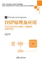
LQFP封装的引脚名称分配如图1-8所示。179球形引脚ZHH-BGA封装的引脚排列如图1-9所示。176球形引脚ZJZ-BGA封装的引脚排列如图1-10所示。

图1-8 F28335 LQFP封装176引脚名称分配

图1-9 F28335-179引脚ZHH-BGA球形封装底视引脚排列

图1-10 F28335-176引脚ZJZ-BGA球形封装底视引脚排列
LQFP封装对印制电路板(PCB)的要求不高,采用两层PCB就能布局和布线,不仅适合机器焊接,也适合手工焊接,焊上这种封装芯片,不需要专用工具就能拆卸。
F28335的3种封装引脚信号按功能划分为:JTAG接口引脚信号说明如表1-5所示;Flash相关引脚信号说明如表1-6所示;时钟模块相关引脚信号说明如表1-7所示;复位相关引脚信号、ADC模块相关引脚信号、CPU和I/O电源引脚信号等说明如表1-8~表1-10所示;GPIO和外设引脚复用信号说明如表1-11所示。
表1-5 F28335-JTAG引脚信号说明

表1-6 F28335-Flash相关引脚信号说明

表1-7 F28335-时钟模块相关引脚信号说明

表1-8 F28335-复位相关引脚信号说明

表1-9 F28335-ADC模块相关引脚信号说明

表1-10 F28335-CPU和I/O电源引脚信号说明

续表

表1-11 F28335-GPIO引脚和外设引脚复用信号说明

续表

续表

续表

续表

续表

续表
